Recent Topics
- Does cell phone interference work?
- Can cell phone jammers interfere with cell phone and wifi signals at the same time?
- Which is better with handheld portable jammers or desktop jammers
Keywords Search
Jammer Blogs
- Drone jammer - drone killer
- The method to solve the problem of intrusive or cell phone
- World strongest anti drone system is important in the military
Popular Products
GSM jammer circuit for mobile phones
News
Before we have talked about mobile phone jammers website production, introduced the GSM mobile phone jammers for you here, here to provide you with the circuit diagram of the GSM jammer for sale device, you can easily understand and make your own signal jammer, if you have any questions, you can buy from here a jammer belongs to you. Jammer-buy is a professional sales signal jammer that you can safely purchase.
Cell phone jammer, that is, the circuit is actually disrupting abbatterne cell frequency, the purpose of receiving and sending in 20 to 30 meters on the function of all mobile devices will not be able to make or receive phone calls and text messages emitter (except for emergency calls).
Described integnato NE555 generated by via the decoupling capacitor C1 is sent to the noise of the oscillator signal's VC1 rotation (30 pf variable capacitor) can change the frequency to 800 MHZ from 2 GHZ disrupt (a third and it is your 900 MHZ).
If necessary, to replace the NE555 can be connected to the preamplification microphone capsule, becoming the audio transmitter, it can receive and UHF scanner's VC1, C4, L1 and L2 is the key to work within the scope of the circuit but not all of the components are ready, but on the Internet is everything, especially the L1, L2 and Q1 SMD components is the most difficult to find.
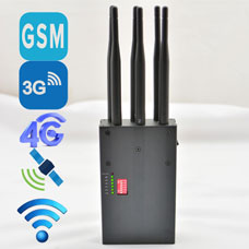
Click on the select GSM 3G 4G cell phone signal jammer.
Realizazione advice:
Create printing it as accurate as possible, obtain a good welding and the use of small pond, I suggest close the circuit in a small metal box, perhaps the on/off, and lead to beautify the whole, as the antenna to increase a switch you can use the old cell phone. If you want to use feed 9V circuitry (e.g. battery) just elimare C7, U2 and its position, make the jump line between the pins 1 and 3, from J2 always feeding the circuit.


